There were some booster designs out there, but none had the things I wanted:
- NMRA DCC signal handling
- Few components
- Photocoupler on input
- Current and thermal protection
- Single +14V= source
- Shut off when no digital input signal present
- Parts availabe in Stockholm
I did not need:
- Motorola compability, but it might work
I thought that the LMD18200 looked promising already, and when I found another design with the LMD18200 I was convinced that this was a way to go.
I want to thank Thomas Nyström for the help with the photocoupler and the alternate current detecting stage. If you need a person who can design electronics with the right touch he is your man.
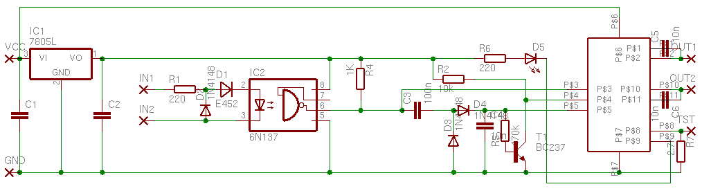
So now I have an own design. About 25 parts, thanks to the motor driver LMD18200. (Drawn with EAGLE )
The whole project in EAGLE format This archive
contains postscript files describing copper mask and hole placement, too.
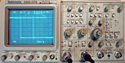
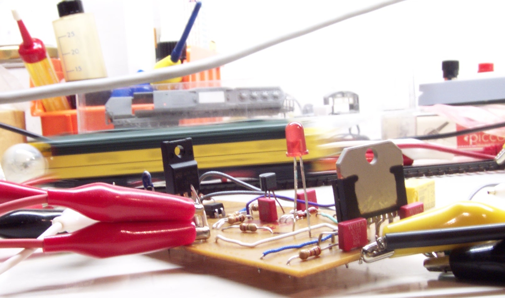 First test! The E8 in the background is run with DDL and the booster prototype.
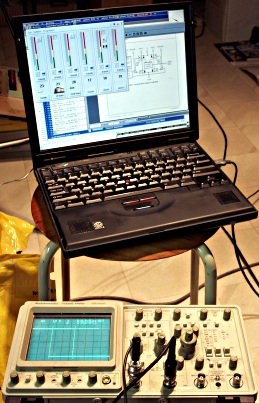 The DCC signal is generated on this laptop's serial port and the output
of the booster is monitored on the scope.
The DCC signal is generated on this laptop's serial port and the output
of the booster is monitored on the scope.
You see the dcltiny and the data sheet of the LMD18200 on the screen. You can
not see the erddcd.
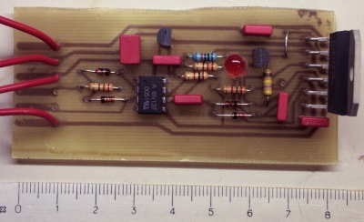 The first "real" one made with a PCB from the CAD layout.
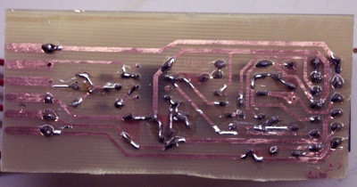 There is another side which might be of interest even if
it is not that nice to look at.
There is another side which might be of interest even if
it is not that nice to look at.
Function
The input signal, a square wave somewhere in the vincinity of +-5 to +-12V is fed into the photocoupler IC2. D1 keeps the current nice and steady and D2 prevents any nasty back currents. Do not try to substitute the photocoupler for a cheper and slower type. It may or may not work depending on what pulse length delays you get from the photocoupler. Often the delays are different for rising and falling flanks.
This photocoupler is strong enough to drive our effect stage, in this case the direction pin of IC3 and the current sensing circuit directly. IC3 is an integrated H-bridge with current limit and temperature protection. It is alternating the output voltage at the same beat as the direction pin is going high or low. As the undervoltage detection circuit of IC3 shuts of at 9-11V=, you must supply this compontent with at least that much. 12.5V= is a good supply voltage for N scale as that will yield in a nice 12V top to top at the output. Where best to get 12V= is another project. The right transformer with a diode bridge and a 2200µF capacitor does the trick for me right now.
Because we only want to enable IC3 when there really is alternating current at the input, we need a way to detect that. C3 filters the DC part and the D4/D3 arrangement keeps only the positive half to load C4. As long as our input signal is present C4 is loaded and keeps the enable input of IC3 active. Because of the high impedance of IC3, R5 is needed to empty C4 faster when there is no signal coming in. To make the H-bridge shut of completely when enable drops, the brake signal must be set when the enable is low but not otherwise. T1 does that.
Last not least, IC1 is providing stable 5V.
Pin 8 of IC3 is a load sensing pin, however I have not tested what signal is present there.
Parts list
R1 220  Ohm
R2  10 KOhm
R3 nope
R4   1 KOhm
R5 470 kOhm
R6 220  Ohm
R7 2.7 KOhm

C1   1 µF
C2 100 nF
C3 100 nF
C4  10 nF
C5  10 nF
C6  10 nF

T1 BC237 or other NPN small signal transistor
D1 E452 Current limiting diode (PDF)
D2 1N4148 (or other fast signaling diode)
D3 1N4148 (or other fast signaling diode)
D4 1N4148 (or other fast signaling diode)
D5 LED (red standard 1.2V 25mA 5mm)

IC1 7805 (voltage regulator +5V) 1.5A TO-220 (PDF) or 0.1A TO-92 (PDF)
IC2 6N137 (fast photocoupler) (PDF)
IC3 LMD18200 (motor driver 3A) (PDF)